Laser-Cut Assembly Instructions
Step 0
If your Solar Motion Simulator was laser-cut, you should see something like the following:

If not, you can cut it out by hand using a scissors. Skip to Step 2.
Step 1
CAREFULLY punch out all parts. Be especially careful for the smallest rectangle with the butterfly-shaped inserts. You may find it helpful to use a long fingernail or a pen to help you remove these small inserts. When done, you should have something like the following:

Step 2
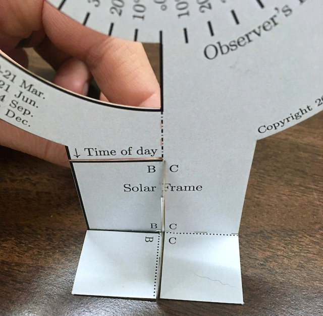
Construct the Base Support. First, fold the "feet" of the Solar Frame so that pairs of letters come together (a valley fold). Fold the other foot in the opposite direction. For example, there are two letter Ds and a letter A near each other at the foot of the Solar Frame on one side. Fold the line between the Ds so that the Ds come together, as shown below.


Each pair of "feet" of the Solar Frame and the Base Support pieces will point in opposite directions, as shown below.

Step 3
Insert the slit on the top of the Base Support into the slit at the bottom of the Solar Frame. When oriented correctly, one "quadrant" should have three matching letters (A, B, C or D) in the inside corner.

Step 4
Tape the feet together to give your model a strong foundation. Tape pairs of feet together from below — one pair of feet at a time. It is important that the feet are level when taping them together. It helps to make sure they are level at the outer edge.

Step 5
Insert the Time Dial into the Solar Frame. You will see a slit near the "neck" of the Solar Frame just below the "Time of day" indicator. When done correctly, the A, B, C and D letters should match the letters of the "quadrant" in the Base Support (see Step 6).


Step 6
Attach the Time Dial to the Solar Frame. You can do this in several ways, but I prefer to place a small piece of tape at the end of the slit on the Time Dial and fold the tape over.

Step 7
Fold the "Attach here" pieces in the center of the Solar Frame. Note that the dotted and dashed lines show you whether to make a mountain fold or a valley fold. See the two images below for clarity.


Step 8
CAREFULLY use a finger to fold the "teeth" of the Observer's Horizon downward (towards the QR code). They should not fold to their base, but only about halfway along their respective length. They will help provide friction to keep the Observer's Horizon disk from slipping.


Step 9
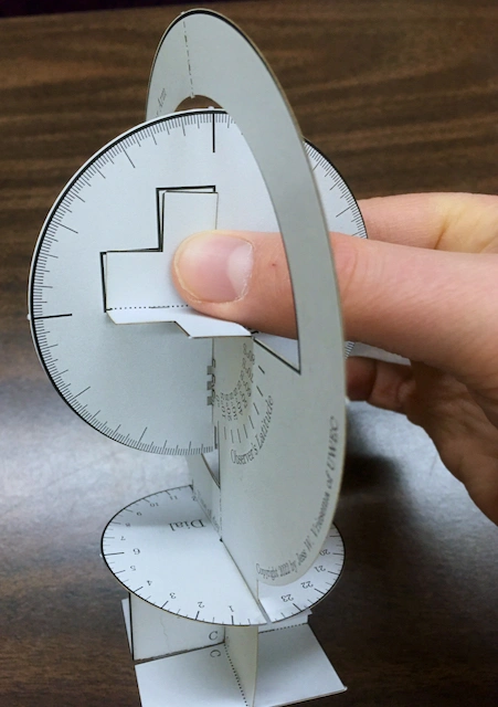
CAREFULLY slide the slit of the Observer's Horizon disk over the center flap of the Solar Frame so that the "Attach here" point on the flap you just folded is aligned with the "Attach here" text on the bottom of the Observer's Horizon disk, as shown below.

Step 10
Carefully place the "Attach here" flap to the bottom of the horizon disk and use a piece of tape to attach them. This is tricky to do! It might help to ask somebody to help hold part of it for you while you tape. A single piece of tape is usually enough, but it may help to secure it on both ends of the L-shape.

If done correctly, you should now be able to swivel the Observer's Horizon disk along the Observer's Latitude track. (High five!)
Step 11
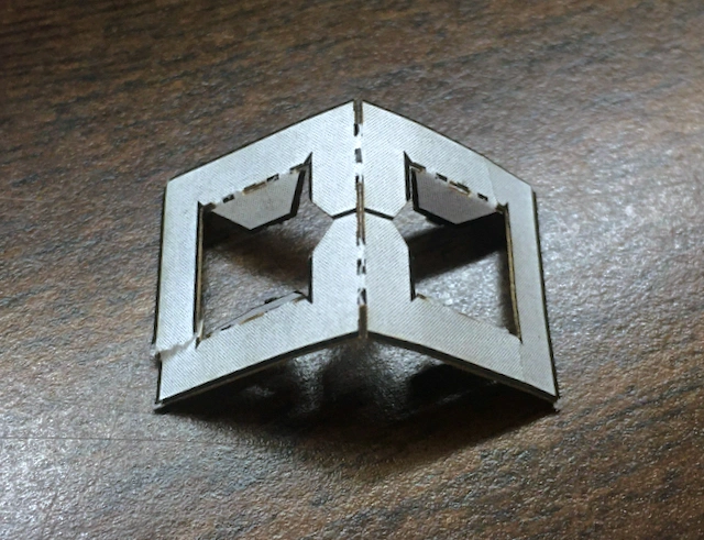
Construct the Solar Slider. First, CAREFULLY fold the flaps inward on one side and fold in half along the center line, as shown below. You may find it helpful to use a pen or pencil to help fold the flaps inward. If the piece rips or tears, you can use a small piece of tape to put it back together.
Step 12
Put the Solar Slider on the Solar Arm as shown below, with the vee pointing towards the Observer's Horizon. The spine of the fold will be on the inner side of the model.
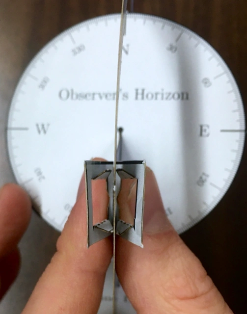
Use tape to attach the two halves of the Solar Slider on the outer side, so it's wrapped around the Solar Arm.

Step 13
Fold the top and bottom of the Solar Arm like a two-way hinge — both a valley and a mountain fold. It should be able to fold completely back on itself in either direction.

Step 14
Write your name on the foot and congratulate yourself on being done! Nice work!
You can watch this video to learn how to use your Solar Motion Simulator!